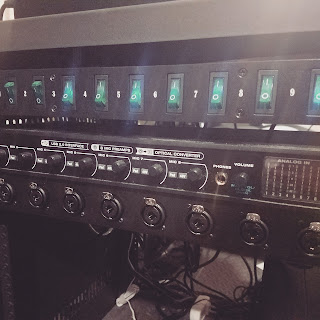
DIY Patch panel!
 |
To give you more context; I have a rack bay where I store my MOTU 8pre interface. The 8 mic/line ins are on the back of the unit, which is perfectly fine, unless your rack unit is twice the depth of the interface. Reaching in to change mic cables was cumbersome and annoying. I decided to look for a snake to move around the front for easy access. After a deal of research I only found bricks for stage use and patch bays that are much too large for my application (16+ mic only lines) so, I decided to go the DIY route. Here I'll give you a break down of the materials I used. some resources I found and how I went about assembling it.
DISCLAIMER: I am no means a professional electrician. I assume you have the basics down of using a soldering iron and a wire stripper.
First off, a list of parts:
1. The rack plate and Neutrik Mic/line in inputs.
 The MOTU 8PRE uses Neutrik Combo (pictured right) great inputs that can take a Mic in and a 1/4 inch plug. Since these jacks are made to fit a board, I found it extremely difficult to find a rack plate that would fit these smaller inputs. I eventually found a package deal on ebay, link here
2. Mic cable!
I decided to go with the Rapco cable on Amazon, which turned out to literally be the Livewire Advantage cable. It's .30 cents a foot, I grabbed 20 feet of it for $6.00.
3. Male XLR plugs
Again I went with Neutrik plugs (thats what livewire uses)
4. Heat shrink and electrical tape
Heat shrink is a precaution, these are small tubing that shrinks when heat is applied. It provides a seal around whatever youre working on, great for the leads.
 First, strip and attach the leads to the 3 colored posts pictured. (looking something like this, cable coming from the mic cable might be blue instead of black)
Next, cut the mic cable into 2 foot increments. No real reason for that length other than leaving enough slack to put the panel on the front or the rear of the panel.
Before we attach the cable to the panel, lets go ahead and attach the male XLR ends to the cables.
Always put the boot of the XLR plug on after you strip the mic cable! otherwise you cant attach it.
There are only 3 leads to wire to, I'll let the diagram speak for itself. (Remember to tin ahead of time)
This youtube link best shows how to assemble the XLR housing.
After you're done assembling all the XLR plugs, you should have a nice cluster of cables! You can check to see if your connections are good by using a multimeter, pressing one node against one end of the wire and one against the other, a reading of 0 will tell you the connection is solid.
 Now we can attach the other end of the mic cable to the inputs themselves. In the diagram above, it shows the colored leads. Attach the corresponding colors from the cable to the leads. The black dots in the diagram indicates where the wires are attached. Take these points, bend them into place, and solder them to the 'C' shaped poles labeled '1' '2' and '3'. These posts are the 1/4 inch leads, so in order to use a 1/4 inch plug, these have to be connected.
Your input jacks should look something like this! Remember to throw on that heat shrink!
Here are a couple wiring videos I found to help clarify things:
Combo Jack wiring Part 1
Combo Jack wiring Part 2
All in all this took me about 4-5 hours to do. Not a long project if you take it step by step and tin everything before you begin working. In the end it saves space when working so you aren't constantly working around other parts and pieces.
That's it! I hope this helped some people understand the process and maybe made you want to jump into a project of your own!


Comments
Post a Comment